In the blast furnace, iron ore (in the form of sinter, pellets, and lump ore) and coal (in the form of coke and pulverized coal), and flux (alkaline or “basic” materials, typically burnt lime or dolomite, which react with impurities to form slag that can be separated) are injected into the top of the blast furnace, flowing downward into contact with upward-moving, hot, CO-rich gases at about 900 to 1300 ℃. Through this process, the iron ore (Fe2O3) is reduced into elemental iron, and the iron is mixed with carbon monoxide (CO) from the flue gas. Carbon (supplied by coal and coke) acts as a reducing agent. The molten, carbon-rich (4-5%) pig iron (also referred to as hot metal) that is produced in the blast furnace is then oxidized in a basic oxygen furnace, in an exothermic oxidation reaction as pure, hot oxygen is blown over the metal, to reduce the carbon content to below 2% (often less than 1%, depending on final product specifications). Liquid crude steel is then tapped from the furnace, and slag (a byproduct, a mixture of metal oxides) removed. Coke (a high carbon content fuel, with most impurities present in coal removed) can be made onsite by heating coal in a coke oven to a high temperature (typically around 1000 ℃) in vacuum conditions, or can be purchased from an offsite coke oven. In this configuration, CO2 is captured from the flue gases of heaters for coke oven batteries, hot stoves, lime kilns, and steam generation units, using post-combustion (end-of-pipe) capture technology, reaching about a 60% reduction in CO2 emissions compared to the baseline case. For the purposes of this factsheet, chemical absorption using MEA solvent has been considered as the capture technology. Off-gases from the blast furnace and basic oxygen furnace are assumed to be used (as is current practice) for energy purposes on-site, either through reinjection into the coke oven, pellet plant, or blast furnace, or by combustion to produce heat and power. CO2 capture at those utilities is also technically feasible, but is not covered in this factsheet.
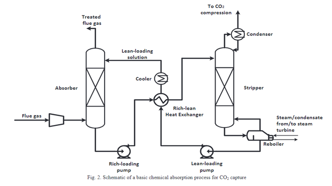
Post-combustion capture does not require any major modifications to the steelmaking process; MEA amine stripping technology is simply added to the plant to capture CO2 from existing flue gas streams. The modifications required for CO2 capture are cleaner flue gas (additional NOx and SOx scrubbing equipment); a CO2 capture unit (absorber and stripper columns, heat exchangers, condensers, and a reboiler); and a CO2 compression and dehydration unit. As the capture process requires electricity (notably for compression) and steam (mainly for solvent recovery), additional investments may also be required to expand the site’s utilities. This factsheet does not specify the utility configuration, but provides additional electricity and steam demand for CCS.
The cleaned flue gas enters the absorber and is brought into contact with the MEA amine solution. About 90% of the CO2 is absorbed into the amine solution (now together referred to as a rich loading solution), and is then pumped to the stripper. In the stripper column, the rich loading solvent is heated with steam from the reboiler (which uses a heat exchanger to transfer heat from external steam to a heat transfer fluid), breaking the chemical bonds between the amine solvent and the CO2, and causing it to release CO2, creating a relatively pure CO2 stream. The CO2 continues to the compressor, which compresses the gas to about 110 bar/11 MPa for transport and storage. The remaining solution (called a lean loading solution), now at a temperature of about 120 ℃, is pumped back to the absorber to begin the cycle again, first passing through a heat exchanger to preheat the rich loading solution.
All information in the datasheets is also available in ESDL (Energy System Description Language). You can find them in the Energy Data Repository (EDR).
